
|
|
If you just place an orthopedic implant into a human being without considering the flexibility of the replacement bone, then you risk what is known as “stress shielding”.
This is due to a phenomenon called “Wolff’s Law”, where the natural bone becomes less dense due to the variations in stress from the implant. The surrounding bone adapts to the stress and remodels its mesostructure via a process of bone resorption. The mismatch between the material densities and flexibilities can result in dense growth areas of the bone and can result in pain for the patient, and ultimately rejection and removal of the implant.
It is therefore important to ensure that the replacement implant matches the flexibility of the bone being replaced. Load carrying implants must be compliant.
One method of doing this is by use of topology optimization and additive manufacturing, where the trabecular structures of the bone can be replicated (to some degree). It’s better than a solid titanium bone, basically. The trabecular beams in the implant allow a certain amount of flex, while remaining lightweight and comfortable for the implantee.
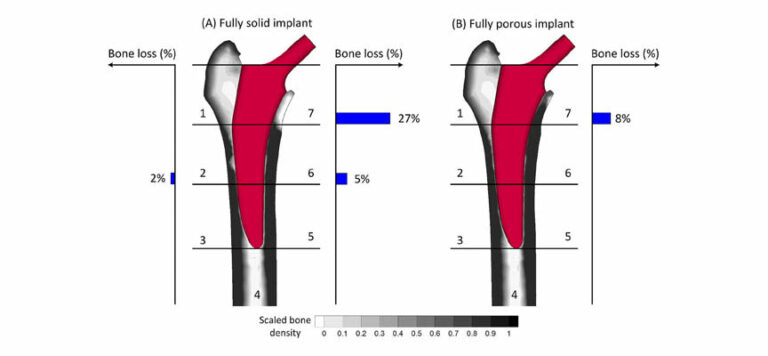
The image below shows the difference in bone loss between a solid titanium femoral implant, and a fully porous 3D printed titanium one.
Another point worth noting is that solid structures have difficulty with osseointegration. A porous structure allows the bone to merge with the implant better.
All in all, porous, printed metal structures have a lot to offer the world of prosthetics.
Let’s take a look at the behaviour of some of these structures under load, and how engineers are making solid, inflexible materials such as titanium… flexible!
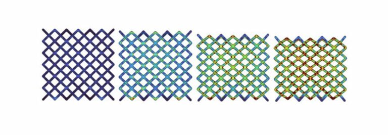
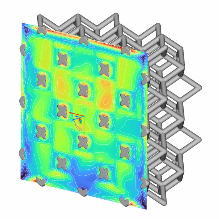
The image below shows a Von Mises plot of a 3D printed lattice structure undergoing compression.
If this was a solid lump of titanium, there would be no flexibility. Take that lump of titanium, and roll it into a thin wire, and it is flexible.
This is effectively what we are seeing in the image above. The individual members in the lattice have enough flexibility to deflect under load, while remaining within the undeformed. The beams bend back into place when the load is removed, just like any other Hookean material.
When you stack these beams up, like in the lattice, then the total deflection is basically the cumulative deflection of the individual members. One layer deflects and the remaining force is sent into the layer below, which deflects, and so on…
By investigating the stress and displacement parameters at differing compression values, the stress and displacement fields can be combined mathematically into a function.
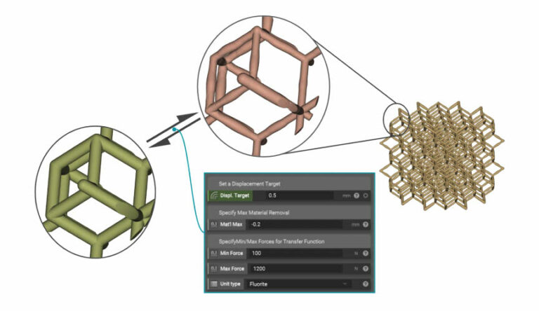
Once that function is determined, engineers can tune the structure computationally (with topology optimization or generative design) to provide a custom set of outputs for a specific batch of inputs, perfectly tailored to the patient’s needs.
As you can see in the image above, the parameters of interest in this case are the displacement target, maximum/minimum force, and amount of material removal required.
The end result is a custom mesostructure that can flex and deflect according to the designer’s requirements, and a happy implant patient who can now walk comfortably without worrying about needing their femur or hip bone changed again in another 5 or 10 years.
